This idea is motivated by something that comes up often in the world of surveying. Not always do we have simple straight lines, and not always do we have a simple plane. Here is an example of the situation in plan view:
You may know that three points define a plane and that an arbitrary fourth point, may not be on the same plane. We can unambiguously define the elevation of every point on the outside of our rectangle by "stringing a line" (which is surveyor-speak for
straight interpolation). We want the elevations we would get if we pulled a string really tight all the way around the outside of the rectangle. (If you care about the units, call them meters, but they are not really the point of this example.)
What about arbitrary points on the interior of the rectangle? It is possible to use interpolation schemes to determine the elevation of a point on the interior of a plane such that it will coincide with the plane. But in the above situation, we have four points that are not coplanar. A common, and highly adaptable, solution to this problem is to break our region up into triangles. There are two ways we could do this.
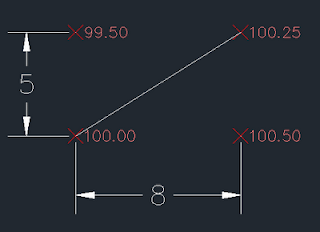 |
| Case 1 |
Notice that in case 1 the elevation at the midpoint of the diagonal line would be 100.125
m.
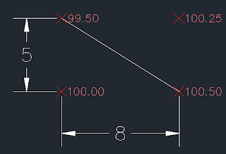 |
| Case 2 |
On the other hand, the elevation at the middle of the diagonal line drawn in case 2 would be 100.000
m.
The general case of this sort of procedure - breaking a region up into triangles - is called creating a triangular irregular network (TIN) and is a well established method. The fact that there may be multiple solutions which are not equivalent does not normally concern us. We just pick one that works because all we care about is that the water will run. In a complex plan, it is not uncommon to see the choice of lines given on the plan. As a surveyor you like to see that as it mean the ambiguity of your job is largely removed.
When it comes to disadvantages, the first thing that is noteworthy about the TIN is that triangles and graders (or their operators) do not like each other very much. Although the grader is a very versatile machine, it still likes following a line. Rectangles are ideal. Look up at case 2 and pretend you're driving a grader, starting from the SW corner and proceeding to the SE corner. As you approach the SE corner, you have a problem: you've got two edges that you are trying to put the blade against. This is frankly infeasible. If this is a very large area (5 miles by 8 miles), we don't care, because the tricky spot is so small compared with the total area. For a smaller area, this might be significant. So what happens? The watchword is "blend", which basically means the grader operator is supposed to figure it out himself and "make it work."
So, can we model this "blending"? (I don't mean just at the diagonal edge, I want to get rid of that.) Can we figure out what the math looks like that describes the result which the grader (operator) would produce if given four corner points on a small, rectangular area and told to "blend" and "make it work"? If we can do this, then we can apply this same method to areas too big for the grader to cover in just one or two passes. Or apply it to the problem of setting grades on concrete islands that are on such a surface. I call it a
twisted plane and it allows us to completely discard the diagonal line.
A twisted plane is a surface formed by using a line (segment) and "sweeping" laterally while changing its angle. The line segment is just like the blade of a grader running from one edge of the rectangle to the opposite side. If the width of our rectangle was exactly the width of the grader blade, it would begin with north end of the blade at elevation 99.50
m and the south end at 100.00
m at the west edge of the area. As the grader proceeded to the east the blade would gradually change its angle from having 0.500
m fall from south to north to having 0.250
m fall from the south to north. (The realities of grading are somewhat swept under the carpet for the sake of simplicity.) Here is an attempt to show what the terrain would look like:
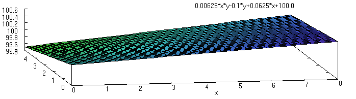 |
| GNU plot of "twisted plane" performed using Maxima |
We will now proceed to develop the equation which describes this surface. Let's start with a fresh diagram that uses variables in it:
For completeness, here are the equations for the elevations of the north, south, east, and west line elevations (we take the south-west corner as the origin):
Now, to determine the elevation at any point on the interior, we can use the west and east lines and do straight interpolation across them like so:
This produces the equation:
If we were to use the north and south lines and interpolate across them instead, we would get:
In both cases the resulting equation is


