The simplest way to visualize this is to imagine a plane that intercepts the prism at a single edge first and has its steepest slope in the direction of the opposite edge:


where the blue square is the cross-section, the red parallelogram is the intersection of the above described plane through the square prism when viewed in that plane. (A few thought experiments of your own will probably serve you better than any further illustration of this phenomenon I could drum up at the moment.)
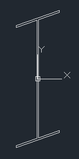
It is interesting to see the result in an I-beam shape if you use a 45° miter and 45° bevel:
As a matter of where this observation fits into mathematics generally, this is a projective or affine transformation. Such transformations preserve straight lines but they do not, in general, preserve right angles.
Aside: Convex Hulls
The fact that they preserve straight lines is a boon to the would-be-writer of a convex hull algorithm in an arbitrary plane since you can project the 3D coordinates onto a simple 2D plane and use the 2D algorithm (being careful to preserve or restore the other coordinate at the end). If you do so, you should probably choose which set of 2 coordinates to use for the algorithm, based on the direction of the plane. For example, if the normal of the plane has a larger z-coordinate than x- or y-coordinates, then the (x,y) pairs are best to use for the information to run the 2D convex hull algorithm on. There are two reasons to be picky about this:
- If the points fed to the routine are in thy yz-plane, you will get incorrect results (if you assumed the (x,y) coordinates should always be used).
- It may reduce the effect of rounding errors in the calculations (in terms of deciding whether points "near the line" of the hull are inside or part of the hull).
(I have lost the original code I used for this post, so I omit references to it now.)
See the Maxima project for download information for Maxima.